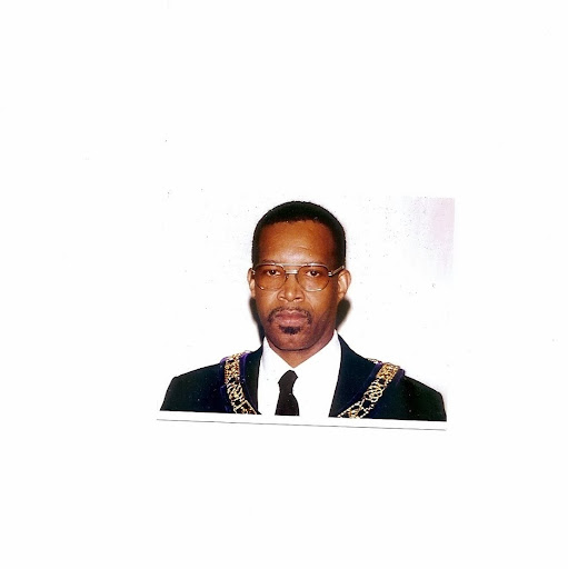
Henry C Tyler
age ~81
from Palm Bay, FL
Henry Tyler Phones & Addresses
- Palm Bay, FL
- Cocoa, FL
- Elkhart, IN
- Chula Vista, CA
- Malabar, FL
Resumes

Henry Tyler
view source
Henry Tyler
view source
Henry H{Hank Tyler
view source
Henry H Tyler
view sourceEducation:
Mcadory High School ///// Uab / Rti 1972 - 1974

Henry Tyler
view source
Henry Tyler
view sourceName / Title
Company / Classification
Phones & Addresses
Incorporator
DRS. MEENA AND TYLER, PA
Bucksville Plaza, LLC
DEVELOP/LEASE/BORROW FUNDS & MANAGE RETAIL SPACE
DEVELOP/LEASE/BORROW FUNDS & MANAGE RETAIL SPACE
Us Patents
-
Overspeed Governor For An Electronic Controlled Fuel System
view source -
US Patent:48376973, Jun 6, 1989
-
Filed:Jul 31, 1987
-
Appl. No.:7/080728
-
Inventors:Soraya Eisa - South Bend IN
Joseph Peczkowski - Granger IN
Henry Tyler - South Bend IN
Glenn Richardson - South Bend IN -
Assignee:Allied-Signal Inc. - Morristown NJ
-
International Classification:F02C 938
-
US Classification:36443102
-
Abstract:A fuel management system (34) for a turbine engine (10) having a metering valve (50) controlled by the input of an electronic computer (36) to a resolver (48). A head sensor (64) responds to pressure differential across the metering valve (50), to control a bypass valve (80) which allows a portion of the fuel available from a supply conduit (58) to return to a reservoir (28). An overspeed governor (116) receives an input turbine (10) to position a cam (120) having four contours (154, 156, 158, and 160) thereon. The first contour (154) provides a feedback to balance the actual speed input. The second contour (156) controls the opening of a proportional valve (122) when the rotation of the turbine exceeds a preset value to allow an operational fluid pressure in the bypass valve (80) to be reduced and additional fuel to flow to the return conduit (95). The third contour (158) controls the movement of flapper valve (128) which allows an integrator piston (124) to move and open an integrator valve (126) to permit a further reduction in the operational fluid pressure such that an additional and corresponding amount of fuel is returned to the reservoir (28). The fourth contour (160) has a linkage (182) connected to the integrator piston (124) and in conjunction with the movement of the flapper valve (128) by the third contour at speeds up to about one half of the normal operational speeds allows the integrator piston (124) to move without opening the integrator valve (126) to provide assurance that the overspeed governor (116) is capable of functioning.
-
Servo Valve Control Apparatus
view source -
US Patent:39675335, Jul 6, 1976
-
Filed:Dec 23, 1974
-
Appl. No.:5/535904
-
Inventors:Henry P. Tyler - South Bend IN
-
Assignee:The Bendix Corporation - South Bend IN
-
International Classification:F15B 910
F15B 1517 -
US Classification:91 49
-
Abstract:A fluid servo network having a servo fluid pressure responsive movable output member controlled by a variable area orifice the effective area of which is established by a movable servo valve which is actuated by lever means in response to a variable force input applied thereto. The lever means includes a main input lever responsive to the variable force input and an opposing variable feedback force which varies in response to the reaction of the output member to establish a force balance on the main input lever. The main input lever is attached to a roller loaded by a constant reference force and movable along a secondary lever mounted for pivotal movement about a fixed axis to vary the effective lever arm of the secondary lever which is attached to the servo valve. The input torque tending to close the servo valve is opposed by the torque derived from a characteristic orifice force unbalance acting through the secondary lever. The forces acting on the secondary lever are isolated from the main input lever thereby making the size and rate of the variable area orifice independent of the force balance relationship of the main input lever.
-
Two-Stage Pneumatic Servomotor
view source -
US Patent:44649762, Aug 14, 1984
-
Filed:Mar 9, 1982
-
Appl. No.:6/356553
-
Inventors:Henry P. Tyler - South Bend IN
-
Assignee:The Bendix Corporation - Southfield MI
-
International Classification:F15B 1316
-
US Classification:91365
-
Abstract:A two-stage pneumatic servo valve assembly for controlling an output motor is disclosed. An input device, such as a torque motor, is coupled to the two-stage servo valve assembly. The first stage of the servo valve assembly includes a vane valve movable by the output of the torque motor to selectively provide a fluid path from an input source to one of the first-stage output channels. The first-stage pneumatic servo valve is coupled with a second stage servo valve. The second stage servo valve controls fluid flow from a pneumatic fluid source to an output motor. The second stage servo valve includes a slidable spool valve movable by fluid received from the first-stage servo valve. A feedback control from the second-stage servo valve to the first-stage servo valve is provided. A second feedback control is provided from the output of the output motor to the first stage servo valve.
-
Control Apparatus Having Overtravel Means
view source -
US Patent:39837602, Oct 5, 1976
-
Filed:May 12, 1975
-
Appl. No.:5/576413
-
Inventors:Henry P. Tyler - South Bend IN
Joseph L. Peczkowski - South Bend IN
Frank J. O'Keefe - South Bend IN -
Assignee:The Bendix Corporation - South Bend IN
-
International Classification:F15B 1524
F16H 2144
F16J 110 -
US Classification:74 99A
-
Abstract:A lever mechanism having an output end and an input end wherein the input end is pivotally mounted to a fixed support and provided with a track portion. The track portion has a spaced apart relationship to the pivot axis of the lever and is provided with a generally V-shaped portion and lateral side portions oppositely extending therefrom. A reference force is applied through a roller member which is positioned along the track by a variable input position signal applied thereto. The apex of the V-shaped portion is on a line through the pivot axis such that with the roller member held in a bottomed position and engaging both sides of the V-shaped portion there is no input moment applied to the lever mechanism and movement of the roller member in either direction from a null position produces a clockwise or counterclockwise motion of the output end of the lever mechanism, depending upon the direction of movement of the output end in response to the roller movement. Engagement of the output end with one of the stops prevents further motion of the lever mechanism and permits the roller member to ride up the corresponding inclined side of the V-shaped portion and along the lateral side portion extending therefrom against the resistance of the reference force thereby allowing overtravel of the roller member in response to the input position signal.
-
Servo Booster Mechanism
view source -
US Patent:45398917, Sep 10, 1985
-
Filed:Mar 19, 1984
-
Appl. No.:6/591151
-
Inventors:Peter V. Colan - South Bend IN
Kenneth L. Miller - South Bend IN
Henry P. Tyler - South Bend IN -
Assignee:Allied Corporation - Morristown NJ
-
International Classification:F15B 1517
-
US Classification:91 49
-
Abstract:A servo booster mechanism (18) having a piston (48) responsive to movement of a plunger (84) by an input signal for controlling the rate of fluid flow past a seat (82) into a passage (80) for distribution to the surrounding environment. A first restrictor (75) creates a first pressure drop in a supply fluid pressure P. sub. s to present an operational chamber (46) with fluid at a pressure P. sub. x. A second restrictor (openings 74-76) creates a second pressure drop in fluid pressure P. sub. x supplied from the operational chamber (46) to present control chamber (88) with fluid at a pressure P. sub. h. The difference in pressures combine to act on the piston (48) and plunger (84) to provide a constant force at stem (26), which provides a feedback to the input member (12), and provide a linkage (22) with a force to hold a position sensor (24) in a stationary position.
-
Method And Apparatus For Optimizing The Operation Characteristics Of An Engine
view source -
US Patent:47455535, May 17, 1988
-
Filed:Dec 24, 1984
-
Appl. No.:6/685626
-
Inventors:Elizabeth A. Raven - South Bend IN
Henry P. Tyler - South Bend IN
Francis G. Sollman - Jacksonville FL -
Assignee:Allied Corporation - Morristown NJ
-
International Classification:F02D 3700
-
US Classification:36443105
-
Abstract:An engine control method and apparatus for optimizing an operating condition of an engine. A plurality of engine variables are determined and operated upon to direct the control of engine effectors so as to place the engine in an optimum operating condition. In particular, the engine effectors are controlled to minimize the fuel consumption of an engine operating at a steady-state. The system selectively moves a pair of engine effectors so as to determine the sensitivity of the engine variables to changes in effector outputs. Such sensitivities are updated during the system operation. The engine effectors are selectively moved as a function of the engine variable sensitivities in a direction to minimize fuel consumption without violating any predetermined operating limits of the engine variables. Once an optimum operating point is obtained, the system remains at rest and checks for changes in operating conditions that may require a new optimum to be determined.
Lawyers & Attorneys

Henry Tyler - Lawyer
view sourceOffice:
Maalouf Ashford & Talbot, L.L.P.
Specialties:
Initial Public Offerings
Foreign Investment
International Business Law
Foreign Investment
International Business Law
ISLN:
921208257
Law School:
King's College School of Law, LL.M., 2004
Googleplus

Henry Tyler

Henry Tyler
Tagline:
If I die, you are forgiven

Henry Tyler

Henry Tyler

Henry Tyler

Henry Tyler

Henry Tyler

Henry Tyler
Plaxo

Tyler Henry
view sourceNorman, OK
Youtube
Classmates

Henry Tyler, Walker Middl...
view source
Milwaukee High School of ...
view sourceGraduates:
Stefan Clisson Guiden (1997-2001),
Henry E Tyler (1985-1989),
Kelly Korpela (1983-1987),
David Gonzalez (1982-1986),
Corey William Roos (2001-2005)
Henry E Tyler (1985-1989),
Kelly Korpela (1983-1987),
David Gonzalez (1982-1986),
Corey William Roos (2001-2005)

Henry Winston Tyler
view source
Henry Tyler
view source
Henry Tyler
view source
Henry Tyler
view source
Henry Authur Tyler
view source
Henry Tyler
view source
Henry Tyler
view source
Henry Tyler
view sourceFlickr
Myspace

Henry Tyler
view sourceGet Report for Henry C Tyler from Palm Bay, FL, age ~81


